MENU
In case you want to know
how I'm doing,
Deer Valley, Arizona
1artworkz's Polishing Writeup
Please excuse the grammatical errors as I rushed to get this done. A more complete version will be posted on my web site.
Physical fact:
The volume of gas that can pass through a hole is limited by the size of the whole and the pressure that is used to push (or pull) that gas through the hole.
I have done this several times in the past to NA engines and I always found an increase in power and over a wider band. The whole idea here is to remove restrictions, port matching and smoothing the surface. My heads were very good castings. I have seen some where the surface was extremely rough.
CAUTION:
Before you start to remove any material, inspect the surface contour of the ports.
You will find some delicate shaping that Nissan has done, especially to the intake ports.
DO NOT remove these bumps.
These surface feature are like rolling hills and shallow valleys.
Before I started to work on the heads I practiced on the intake manifold. If I screwed up here, its replacement costs would be a lot less.
After removing the valves and cams, I washed the heads with a 50/50 mix of mineral spirits and lacquer thinner. In the past, with cast iron heads, one would remove the valve guides. This is difficult to do with aluminum heads. When removing the guides, galling occurs, the valve guide channels have to be machined and new over size guild pressed in.
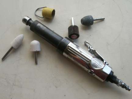
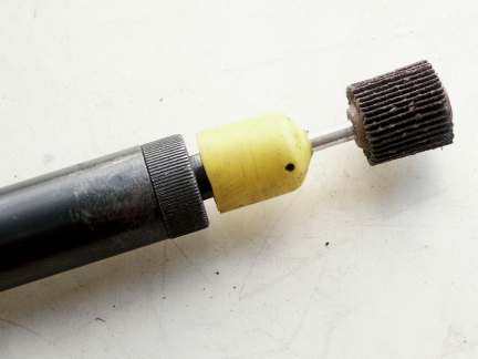
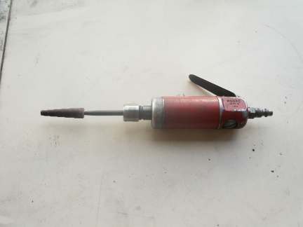
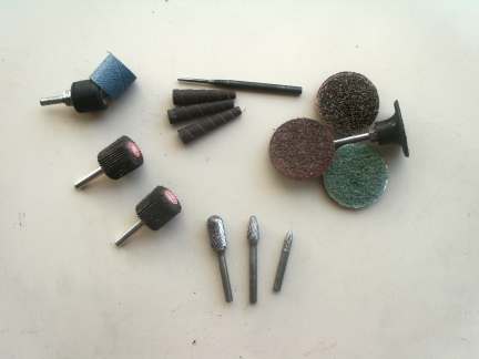
My workbench has two layers of cardboard to prevent any damage to any of the delicate surfaces. I have a very old Devilbiss two stage 3 hp compressor which puts out about 10 cfm at 95 psi. This compressor is just barely able to keep up with my old 1/4" Rodac die grinder. At times, when using the flapper wheels I would have to pause, work on something else while waiting for the compressor to rebuild volume and pressure. Note the different mounted points that were used as seen in pic 5, pic 6, and pic 7.
Using the intake and exhaust gaskets as templets, I scribed a line on the intake/exhaust surface as a limit guide. Because the heads are aluminum, removing excess metal is very easy with a carbide die grinder bit. Almost too easy, as mistakes can be made are difficult to repair.
Using the carbide tip with the 1/4" die grinder I hogged out the aluminum close to my scribed line. Be careful not to nick the valve guides. You will want to spray some light cutting oil or, in my case, I used "Liquid Wrench" to prevent the aluminum from caking on the carbide cutter.
Once you have this completed switch to a 1" x 1.5" mounted flapper wheel, 60 grit, to remove all he tool marks. You'll be able to quickly accomplish this step. Then switch to the 120 grit. For the exhaust port which is smaller, you will need to use a 1" x 0.5", 120 grit, flapper wheel for smoothing on the combustion side. This step will take longer and requires more patience. At the point I switch to 220 grit wet or dry for some hand work on the manifold side of the ports.
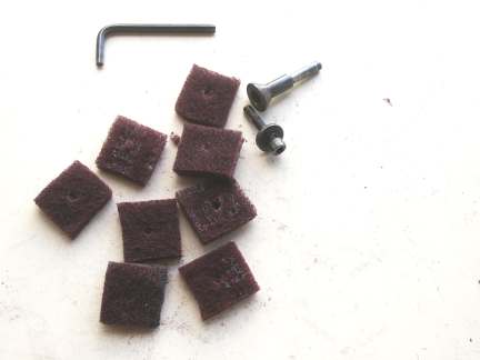
There will be some areas that will be inaccessible to the flapper wheels. It is in these areas where I used the tapered cartages, with grits 120, 220 and 320. This was the most time consuming. After all this, I still was not satisfied with the smoothness of the surface. I looked for 3M "Scotch Bite" finishing wheels (pic 7). I found none so I had to invent my own. Picture "8" is the parts I use to make the wheels. This wheel produced a near polished surface. I could have stopped here.
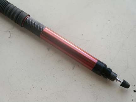
I used my small "Pen" style die grinder with some small 1/8 shaft mounted points to smooth those areas around the valve guides I could not get with the larger tools.
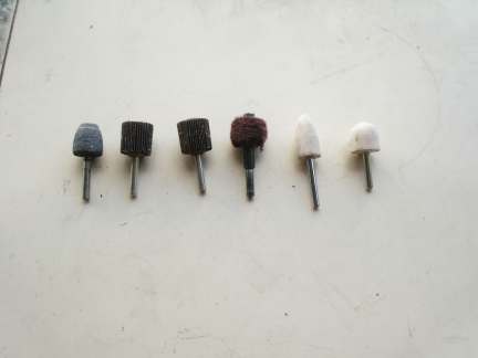
I finished by buffing the surfaces with mounted buffing bobs. These are made from wool and come in a verity of shapes. I used two grades on buffing compound, Black rouge for fast cutting and green rouge for mirror bright finish.
For the combustion chamber of the head I used the small 2" disks seen in photo # 6. Be very carful that you NOT change the shape of the chamber or remove any of the shaped bumps. These bumps are there to promote a swirl effect to the fuel air mix as it enters the chamber. Also, do not round over the sharp edges where the head bolts to the block.
Here are the supplies to used, not counting the tools, the carbide grinding points and buffing compound
4 - 1 x1.5" 60 grit 1/4 mounted flapper wheels ...... $1.95 each .... 7.80
2 - 1 x1.5" 120 grit 1/4 mounted flapper wheels ..... $1.95 each .... 2.58
4 - 1 x 0.5 120 grit 1/4 mounted flapper wheels ..... $5.78 each ... 23.00 (burned, bought local)
6 - 1/8" mounted bobs................................ $2.50 each ... 15.00
6 - 1/4" mounted buffing bobs ....................... $2.50 each ... 15.00
25 - .50 x 2", tapered cartage rolls ................ $0.50 each ... 12.50
6 - 2" surface conditioning disks ................... $0.58 each .... 3.48
Total cost $80.00 in materials.
Gary Molitor (1artworkz)

Now I'm going to go work on my Z